
Many DIYers destroy their power systems by wiring an inverter directly to a household breaker panel without a transfer switch. You must wire the DC side to a battery bank using short, thick cables and an inline fuse, while keeping the AC output completely isolated from the grid. Making these connections incorrectly creates severe fire hazards and can dangerously backfeed the electrical lines.
Quick answer
Wire the inverter on the DC side with correctly sized, short battery cables, a fuse or breaker near the battery, and a properly bonded chassis ground. Wire the AC side only according to the inverter manual and local electrical code. Never plug an inverter output into a wall outlet or connect it to a breaker panel without a listed transfer switch or interlock installed by a qualified electrician.
- DC wiring requires heavy-gauge cables and an appropriately sized inline fuse located near the battery.
- Never connect an inverter’s AC output to a household wall outlet or breaker box without a proper transfer switch.
- AC and DC wiring must remain separated and should not share the same conduit.
- Inverter chassis grounding is separate from AC neutral-to-ground bonding.
- Sizing your inverter requires calculating both continuous running watts and high motor starting surge watts.
- How is Inverter Wiring Done?
- How to Wire a Power Inverter to a Battery
- How to Wire an Inverter to an RV Breaker Box
- How to Wire an Inverter to Your House
- Does an Inverter Need to be Grounded?
- Sizing Your Cables and Output
- Can You Wire Inverters in Series?
- Does Installing an Inverter Increase the Electricity Bill?
- How Long Does it Take to Install an Inverter?
- Frequently Asked Questions
How is Inverter Wiring Done?
Inverter wiring happens in two distinct phases: the DC input side and the AC output side. The DC side connects your batteries to the inverter. This side handles massive amounts of current at low voltage. It requires very thick cables and specialized high-current fuses. The AC side distributes standard household voltage (120V or 230V) to your appliances or breaker panel. This side handles high voltage at lower currents. It requires proper transfer switches to prevent power from colliding with grid or generator power.
You cannot mix these two sides. AC and DC wiring should not share the same conduit. Where they must cross paths, Victron recommends crossing them at approximately 90 degrees to reduce electromagnetic interference. Keeping these systems isolated protects your equipment and ensures a clean power signal.
How to Wire a Power Inverter to a Battery
Connecting the DC side is where most DIY errors occur. High-power systems draw massive amps from the battery bank. For a rough DC-current estimate, a 1000 W load on a 12 V battery at 90 percent efficiency draws about 93 A. Because of this high current, you must use short, very large conductors and appropriately rated overcurrent protection.
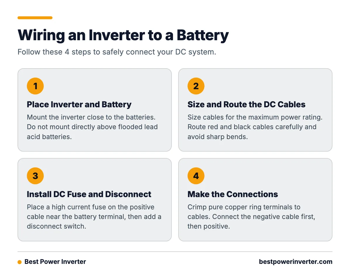
1. Place the Inverter and Battery Bank
Mount the inverter close to the batteries to keep DC cables short. Long cables drop voltage and create excess heat. However, do not mount the inverter directly above flooded lead-acid batteries. The corrosive gases from the batteries will ruin the inverter’s internal electronics over time.
2. Size and Route the DC Cables
Inverter battery cables must be sized for the inverter’s maximum power rating. For a 2000W inverter on a 12V system, you will typically need 1/0 or 2/0 AWG copper wire. Route the positive (red) and negative (black) cables carefully. Avoid sharp bends that can fray the internal copper strands.

3. Install the DC Fuse and Disconnect
The fuse protects the cable, not the inverter. Place a high-current catastrophic fuse (like an ANL or Class T fuse) on the positive cable, as close to the battery terminal as possible. If the cable shorts against a metal chassis anywhere between the battery and the inverter, the fuse will blow and stop a fire. Install a battery disconnect switch between the fuse and the inverter so you can safely cut power during maintenance.
4. Make the Connections
Crimp pure copper ring terminals onto the ends of your cables. Do not use solder alone on heavy-gauge battery cables, as extreme heat can melt the joint. Connect the negative cable first, then the positive. You will likely see a small spark when connecting the positive cable. This is normal; it is simply the internal capacitors filling up. Finally, ensure the battery connections are securely tightened to the manufacturer’s specified torque.
From the Shop
We frequently see melted inverter terminals caused by loose nuts. A loose connection creates high electrical resistance. When 100 amps flow through a loose nut, it acts like a heating element. The terminal glows red hot, melts the plastic housing, and destroys the inverter. Always use a torque wrench and check your connections after the first few hours of heavy use.
How to Wire an Inverter to an RV Breaker Box
Wiring an inverter into an RV electrical system requires separating the inverter’s power from shore power. You cannot simply connect the inverter to the main panel without an automatic transfer switch (ATS). If shore power and inverter power hit the same circuit simultaneously, the inverter will likely explode.
Many modern RV inverters include a built-in transfer switch. These units wire in-line with the main AC feed. When you plug the RV into shore power, the internal switch bypasses the inverter and feeds the panel directly. When you unplug, the switch clicks over, and the inverter starts drawing from the battery.
If your inverter does not have a built-in switch, you must install an external ATS. Wire the shore power input to the primary side of the ATS. Wire the inverter output to the secondary side. Connect the output of the ATS to your RV breaker box.
When running wires to the panel, use copper conductors rated for the installation voltage and temperature. For example, Victron’s panel guidance specifies using wire rated for at least 150 V and 75 degrees Celsius for 120 V AC systems, and 300 V and 75 degrees Celsius for 120/240 V systems.
How to Wire an Inverter to Your House
Homeowners often want to use battery power during grid outages. An inverter’s AC output must never be connected to another AC source, including a household receptacle or generator, because this can backfeed the source. Backfeeding sends your inverter’s voltage out onto utility lines, which can kill line workers repairing the grid.
According to safety manuals, such as the Inverter VE.Direct 120V Manual, you must use listed, code-compliant methods to connect to a household panel.
- If you only need a fridge and a few lights: Use a heavy-duty extension cord directly from the inverter’s front outlets. Do not touch the breaker panel.
- If you want to power specific household circuits: Install a manual transfer switch next to your main panel. This locks out grid power to those circuits when the inverter is running.
- If you want whole-house access (managing loads manually): Have a qualified electrician install a generator interlock kit on your main breaker. This physical metal plate makes it impossible to turn on the main grid breaker and the inverter breaker at the same time.
If you use an interlock or transfer switch, you will wire the inverter’s hardwire output terminals to an AC inlet box or directly to the transfer panel switch using outdoor-rated Romex or THHN wire in conduit. Always hire a licensed electrician for panel modifications, as local codes heavily regulate these connections.
Does an Inverter Need to be Grounded?
Yes. Grounding prevents electrocution and equipment damage, but you must understand the difference between chassis grounding and neutral bonding.
Chassis Ground
The metal case of the inverter must connect to earth ground (or the vehicle frame in an RV). If an internal live wire shakes loose and touches the case, the ground wire gives the fault current a safe path away from you. The inverter chassis must be connected to a proper protective ground; some models provide a dedicated grounding terminal on the outside of the casing.
For sizing, a Victron installation manual states that the equipment grounding conductor from the chassis should be at least half the cross-sectional area of the battery conductors. If you use 2/0 battery cables, use at least a #2 or #4 AWG ground wire.

Neutral-to-Ground Bonding
In standard electrical systems, the neutral wire and the ground wire connect at one central point (usually the main home breaker panel). This bond allows GFCI (Ground Fault Circuit Interrupter) and RCD (Residual Current Device) breakers to work correctly. A neutral-to-earth connection may be required for proper RCD, RCCB, RCBO, or GFCI operation, but the exact bond location depends on the inverter and system design.
Some inverters have an internal relay that automatically bonds neutral and ground when running off the battery, and breaks the bond when connected to shore power. Read your specific inverter manual. If you have two neutral-ground bonds in the same system, you will create ground loops, and your GFCI outlets will constantly trip.
Sizing Your Cables and Output
People often buy an inverter based on the running watts of their appliances and completely ignore the motor starting surge. Compressors and pumps require a massive spike in power for a fraction of a second to start spinning.
Consider a standard 1/3 HP sump pump. It might use 800 watts while pumping water. However, when it first kicks on, it can demand 2,500 watts of surge power. If you wire a 1,000W inverter to this pump, the inverter will instantly shut down in overload mode the moment the pump tries to start.
Here is a typical sizing path for a heavy motorized load:
- Identify Running Watts: 800W.
- Identify Surge Watts: 2,500W (usually 2.5x to 3x the running watts).
- Select Inverter: You need an inverter with a continuous rating of at least 1,500W and a surge rating of at least 3,000W.
- Calculate DC Current: 1,500W / 12V = 125 Amps. Add 10% for efficiency losses (125 / 0.90) = 138 Amps continuous.
- Select Cable & Fuse: For 138 Amps, you need at least 1/0 AWG wire and a 175A or 200A inline fuse.
| Inverter Size (12V) | Max Continuous DC Draw | Minimum Copper Wire Size (Under 6 ft) | Recommended Inline Fuse |
|---|---|---|---|
| 1,000 Watts | ~93 Amps | 4 AWG | 125 Amp |
| 2,000 Watts | ~185 Amps | 1/0 AWG | 250 Amp |
| 3,000 Watts | ~277 Amps | 4/0 AWG | 350 Amp or 400 Amp |
Can You Wire Inverters in Series?
You generally cannot wire standard inverter outputs in series or parallel unless the manufacturer specifically engineered them for it. Wiring two basic 120V inverters in series to get 240V will cause a phase collision. The resulting short circuit will blow up both units immediately.
Premium brands offer “stackable” inverters. These units connect via a communication cable. The master inverter syncs its sine wave with the slave inverter, allowing them to output perfectly timed 120/240V split-phase power or double the 120V current. If you need 240V or massive parallel output, you must buy specific models designed to communicate with each other.
Does Installing an Inverter Increase the Electricity Bill?
If you connect a battery backup inverter to the grid so it can charge the batteries, you will see a small increase in your electricity bill. This happens because of standby consumption and efficiency losses.
An inverter is not 100% efficient. When it converts grid AC power into DC power to charge the battery, some energy is lost as heat. Likewise, just leaving the inverter powered on causes it to draw a baseline amount of power (often 10W to 30W) to keep its internal processors running. While this standby drain is small, it adds up over a month. To eliminate this draw, simply turn the inverter off when you are not using it.
How Long Does it Take to Install an Inverter?
A basic DIY installation connecting an inverter to a battery bank for standalone outlet use typically takes 2 to 4 hours. This includes crimping cables, mounting the hardware, and routing the wires neatly.
If you are integrating the inverter into an RV breaker box or installing a residential transfer switch, expect the job to take a full day (6 to 10 hours). Home integration requires careful wire routing through walls, installing conduit, and modifying the main breaker box,a task that requires a professional electrician.
Frequently Asked Questions
how to wire inverter to rv breaker box?
You must route the shore power connection through an automatic transfer switch (ATS) before it reaches the breaker box. The inverter output also goes into the ATS. The ATS then feeds the main RV breaker box. This prevents shore power and inverter power from clashing. Ensure the RV’s battery converter/charger is isolated on a non-inverter circuit.
how to wire inverter to breaker box?
For a home breaker box, you must install a manual transfer switch or a generator interlock kit. Connect the inverter’s hardwired AC output to an exterior inlet box or directly to the transfer panel using appropriate gauge wire in conduit. An electrician must verify the neutral-ground bonding matches local code.
how to wire a inverter?
Wire the DC side by connecting the positive and negative terminals to a battery using heavy-gauge cables. Install a high-current inline fuse on the positive cable near the battery. Wire the AC side by either plugging appliances directly into the front outlets or hardwiring the output to a dedicated, isolated subpanel.
can you wire inverters in series?
No, unless the specific models are designed as “stackable” units with communication cables. Connecting standard inverters in series will result in unsynchronized AC waveforms, causing a dead short that destroys both units.
does an inverter need to be grounded?
Yes. The metal chassis must be connected to an earth ground or vehicle frame to provide a safe path for fault currents. The grounding cable should be at least half the cross-sectional thickness of your main DC battery cables.
how to wire an inverter to your house?
Never use a “suicide cord” to plug an inverter into a wall outlet. You must use an approved transfer switch or an interlock kit on your main breaker panel. This safely disconnects the house from the utility grid before allowing the inverter’s power into the household circuits.
how is inverter wiring done?
Wiring is split into DC and AC sides. The DC side handles low voltage and high amps, requiring thick battery cables and large fuses. The AC side handles high voltage and lower amps, requiring standard Romex or THHN household wiring and strict isolation from the utility grid.
how to wire an inverter?
Mount the inverter near the batteries, connect the negative battery cable, then connect the fused positive battery cable. Attach the chassis ground wire. Keep all DC and AC wiring separated, crossing them at 90-degree angles if they must intersect.
does installing inverter increase electricity bill?
Yes, slightly. Inverters consume a small amount of standby power (usually 10 to 30 watts) to stay active. Additionally, charging a battery bank from the grid involves efficiency losses, meaning you pull slightly more power from the wall than the battery actually stores.
how long does it take to install an inverter?
A simple standalone battery connection takes a DIYer 2 to 4 hours. Integrating an inverter with a transfer switch into an RV or home electrical panel usually takes a professional 6 to 10 hours depending on wire routing and conduit requirements.
Sources