
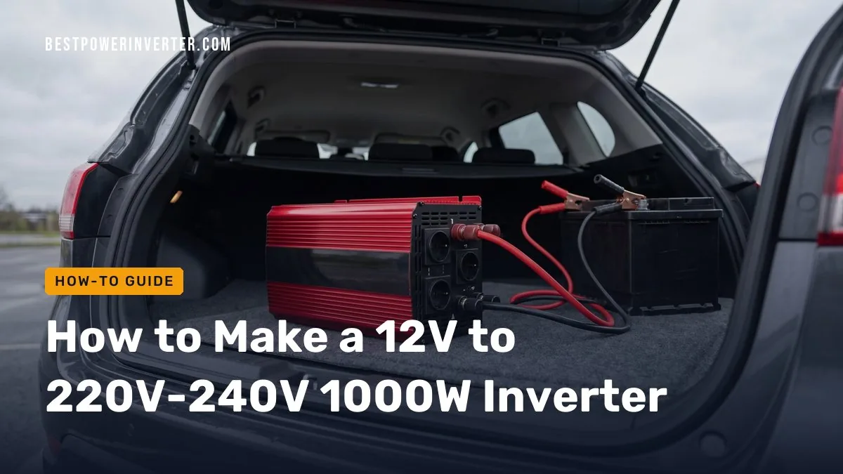
The first decision when you build a 12 V to 220-240 V, 1000 W inverter is the topology. You can use a push-pull MOSFET stage with a heavy 50/60 Hz transformer, or a high-frequency boost stage followed by an H-bridge. Either way, the battery side carries roughly 90-100 A at full load, so cables, fuses and cooling matter as much as the schematic. The output is lethal mains-level voltage, so build it with care.
Quick answer
Build a push-pull or full-bridge MOSFET stage, a step-up transformer or DC-link converter, a feedback loop on the output, and full protection. Fuse the battery cable for about 125-150 A and size every 12 V part for roughly 100 A. Test in stages before any appliance is connected.
- Best for learning: modified sine, low-frequency transformer design
- Best for electronics: pure sine, two-stage design
- 1000 W at 12 V is 83.3 A before losses. At 90% efficiency the battery supplies about 92.6 A.
- Fuse the positive battery cable close to the battery, and use heavy cable with short runs.
- Pure sine output suits sensitive electronics. Modified sine is cheaper and simpler but less friendly to some loads.
- Motors and compressors need a surge rating well above their running watts.
- Feedback regulation, undervoltage cutoff, short-circuit and thermal protection are not optional.
- Test with a current-limited supply and a dummy load before connecting real appliances.
- How Do I Make a 12 V to 220-240 V 1000 W Inverter?
- What Circuit Topology Is Suitable for a 12 V 1000 W Inverter?
- How Many Amps Does a 1000 W Inverter Draw From a 12 V Battery?
- What Battery Capacity and Runtime Are Needed?
- What Components Are Needed?
- What Fuse, Cable Size and Disconnect Should Be Used?
- Should the Output Be Modified Sine or Pure Sine?
- How Can the Inverter Regulate 220-240 V?
- What Protections Are Required?
- How Do I Keep a 1000 W Inverter Cool?
- What Tests Should Be Done Before Connecting Appliances?
- Frequently Asked Questions
How Do I Make a 12 V to 220-240 V 1000 W Inverter?
You build five blocks: a 12 V battery input, a switching stage, a step-up stage, a regulated 220-240 V output, and a protection layer around all of it. Each block must handle about 100 A on the DC side. The AC side is smaller in current, about 4.3 A at 230 V, but it can kill.
Here is the order of work:
- Pick the output type (modified or pure sine) and the topology.
- Calculate input current, battery size and cable size.
- Select the MOSFETs, transformer, driver and control chip.
- Add feedback so the output stays near 230 V.
- Add protections for short circuit, reverse polarity, low and high battery voltage, and heat.
- Assemble in an insulated, earthed, enclosed case.
- Test in stages.
Be honest about skill level. Building a 1000 W unit is a hard project. The high current, the mains voltage and the heat all punish small mistakes. If you have never built a smaller inverter, start with a 150-300 W design first.
What Circuit Topology Is Suitable for a 12 V 1000 W Inverter?
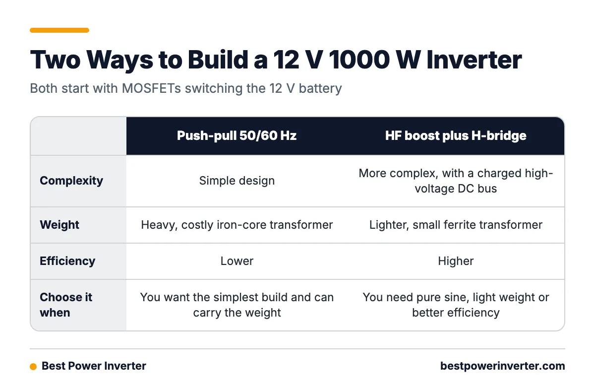
Two layouts work well at this power: a low-frequency push-pull inverter, and a two-stage high-frequency inverter. Both start with MOSFETs switching the 12 V battery.
Option 1: Push-pull with a 50/60 Hz transformer
MOSFETs switch the two halves of a center-tapped primary at the mains frequency. The transformer steps the voltage up directly to 220-240 V. The design is simple and tolerates surges well. The downside is weight. A 1000 W iron-core transformer is heavy and costly.
Option 2: High-frequency boost plus H-bridge
A push-pull stage runs at tens of kilohertz into a small ferrite transformer. A rectifier makes a high-voltage DC link, typically in the 330-400 V range for 230 V output. An H-bridge then turns the DC link into AC, using sine PWM for pure sine output. This is lighter and more efficient. It is also more complex, and it has a high-voltage DC bus that stays charged after shutdown.
If you need pure sine, light weight or better efficiency, choose the two-stage design.
If you cannot measure high voltage safely, buy a certified inverter instead.
A 12 V push-pull switch sees about twice the battery voltage plus ringing spikes. So 40-60 V MOSFETs with very low on-resistance are the usual choice, with several in parallel per side.
How Many Amps Does a 1000 W Inverter Draw From a 12 V Battery?
It draws about 83.3 A with no losses, and between roughly 88 and 104 A once efficiency is counted. Many DIY plans quote 1000 W and skip this step. Do not skip it. The formula is simple: input amps = output watts ÷ efficiency ÷ battery volts.
| Inverter efficiency | Input power (W) | Input current at 12 V (A) |
|---|---|---|
| 80% | 1250 | about 104 |
| 85% | 1176 | about 98 |
| 90% | 1111 | about 93 |
| 95% | 1053 | about 87.7 |
Real battery voltage sags under load. At 11 V, the same 1000 W load pulls even more current. Plan for transients above the table values, especially at startup.

What Battery Capacity and Runtime Are Needed for a 1000 W Load?
A 12 V 100 Ah battery holds about 1200 Wh of nominal energy. That is not all usable, and a 1000 W load drains it fast.
Worked example: at 90% efficiency, a 1000 W load takes about 1111 W from the battery. Dividing 1200 Wh by 1111 W gives about 1.08 hours on paper. If you limit a lead-acid battery to about 50% depth of discharge, the practical runtime is closer to 30-35 minutes. Peukert effect, cold weather and battery age cut it further.
Also check the battery’s discharge rating. Pulling about 93 A from a 100 Ah battery is close to a 1C rate. Many lead-acid batteries struggle at that rate and sag badly. Lithium iron phosphate (LiFePO4) packs handle it better, but they need a battery management system rated for the current.
| Battery | Nominal energy | Rough runtime at 1000 W load (90% efficiency, before real-world limits) |
|---|---|---|
| 12 V 100 Ah, full capacity | 1200 Wh | about 1.08 hours |
| 12 V 100 Ah, 50% usable | 600 Wh | about 32 minutes |
| Two 12 V 100 Ah in parallel, 50% usable | 1200 Wh | about 65 minutes |
What Components Are Needed for the Oscillator, MOSFET Stage, Transformer and Output Filter?
You need a control chip, a gate driver, power MOSFETs, a transformer, and a filter. Choose each for current, not just voltage.
| Block | What to pick | Why it matters |
|---|---|---|
| Oscillator / PWM controller | Dedicated PWM IC or microcontroller with dead-time control | Prevents both switches turning on together, which causes shoot-through and blown MOSFETs |
| Gate driver | Driver with strong peak current and a stable gate supply | Slow gate edges make MOSFETs run hot |
| Power MOSFETs | 40-60 V, very low Rds(on), several in parallel per side | Conduction loss at about 100 A is the main heat source |
| Transformer | Rated above 1000 VA, with proper insulation between windings | Saturation or poor insulation causes overheating or shock risk |
| Rectifier (two-stage design) | Fast-recovery diodes rated above the DC link voltage | Slow diodes waste power and overheat |
| Output filter | LC filter sized for the switching frequency | Smooths PWM into a clean sine wave |
| Capacitors | Low-ESR types on the 12 V side, high-voltage types on the DC link | Ripple current heats cheap capacitors quickly |
Parallel MOSFETs share current only if the layout is balanced. Use equal gate resistors for each device and keep traces short and wide, or use copper bars. Thin traces carrying 100 A will burn.
What Fuse, Cable Size, Connectors and Disconnect Should Be Used on the 12 V Side?
Use a high-current fuse near the battery positive terminal, short heavy cable, rated lugs, and a DC disconnect. Based on the roughly 100 A full-load draw, a fuse in the 125-150 A range is a common starting point, so it carries normal load but still protects the cable.
- Fuse: a Class T, ANL or MEGA-style fuse rated for DC, mounted as close to the battery as possible.
- Cable: fine-stranded copper, sized from the cable maker’s ampacity chart for 100 A or more. Many builders use 35 mm² (about 2 AWG) or larger for short runs. Keep each run as short as you can.
- Voltage drop: at 100 A, even 0.1 V lost across a cable is 10 W of heat. Short, thick cable saves both power and fire risk.
- Connections: crimped or soldered copper lugs, bolted to a busbar. Tighten to the torque the terminal maker specifies. Loose lugs are a leading cause of melted terminals.
- Disconnect: a DC-rated switch or breaker sized for the current. An ordinary AC switch can weld shut or arc.
From the Shop
Common failure points on high-current 12 V builds are not exotic. They are loose lugs, thin wire, and fuses placed far from the battery. A fuse at the inverter end leaves the whole cable unprotected if it shorts. Put the fuse at the source.
Should the Output Be Modified Sine or Pure Sine?
Choose pure sine if you will power electronics, motors with speed control, or anything with a sensitive power supply. Choose modified sine only for simple resistive loads such as basic heaters and incandescent lamps, and accept the limits.
| Feature | Modified sine | Pure sine |
|---|---|---|
| Waveform quality | Stepped, high harmonics | Smooth, close to grid power |
| Build cost | Lower | Higher |
| Motor loads | Often run hotter and noisier | Run normally |
| Sensitive electronics | May buzz, overheat or misbehave | Generally the safer choice |
| Efficiency | Usually a bit higher | Slightly lower due to filtering |
| Complexity | Simple | Needs sine PWM and filter |
Now the surge point. A 1000 W rating means continuous power. Motors and compressors can need several times their running watts for a moment at start. Write down two numbers for your design: continuous watts and peak watts. Do not run a fridge compressor or pump on a unit that only holds 1000 W with no surge headroom. The brief behind many 1000 W claims never separates the two, so check the manufacturer’s data sheet for any inverter you compare against, such as this 12V 1000W inverter specification page.
How Can the Inverter Regulate 220-240 V Under Changing Load and Battery Voltage?
Use feedback. Sense the output (or the DC link) through an isolated divider or transformer winding, compare it to a reference, and let the control chip adjust the PWM duty cycle. Without this, the output moves with the battery.
A fully charged 12 V lead-acid battery sits near 12.7 V at rest, and it drops under load and as it discharges. An open-loop inverter would swing its output with it. Switching losses also change with load. Feedback fixes both.
- Low-frequency design: adjust the PWM width on the drive signal so the RMS output stays near 230 V.
- Two-stage design: regulate the DC link voltage in stage one, then modulate the H-bridge in stage two.
- Isolation: keep the feedback path isolated, or use a divider with safe resistor ratings, so a fault cannot put mains voltage on the control board.
What Protections Are Required Against Short Circuit, Reverse Polarity, Undervoltage, Overvoltage and Overheating?
You need all five, plus a battery-side fuse. Diagrams online often leave these out, and that is where builds fail.
| Protection | How it is done | Typical setting (adjust to your parts) |
|---|---|---|
| Battery-side fuse | DC-rated fuse at battery positive | About 125-150 A |
| Reverse polarity | Series or ideal-diode MOSFET, or a fuse plus a crowbar diode | Must carry full current |
| Undervoltage cutoff | Comparator that stops the PWM | Around 10-10.5 V for lead-acid, with an alarm above it |
| Overvoltage | Comparator on the input rail | Around 15-15.5 V |
| Short circuit / overload | Shunt or current sensor with fast trip | Trip above rated peak, with a hiccup restart |
| Thermal shutdown | Sensors on heatsink and transformer | Set below the part’s temperature limit |
Add an output fuse or breaker and, where local rules require it, a residual-current device on the AC output. Two standards are useful references for what a safe power converter should do. IEC 62109-1 addresses protection against electric shock, energy, fire and mechanical hazards in power conversion equipment. IEC 62109-2 covers particular safety requirements for DC-to-AC inverters in photovoltaic and energy-storage use. A home build will not be certified, but the standards show what to aim for.
How Do I Keep a 1000 W Inverter Cool?
Mount the MOSFETs and rectifiers on a large aluminum heatsink with insulating pads, and force air across it with a fan. A 1000 W inverter at 90% efficiency still turns about 111 W into heat.
- Use thermal paste and insulating pads rated for the voltage involved.
- Leave clear intake and exhaust space in the enclosure.
- Run the fan from a temperature sensor, and shut the inverter down if the fan fails.
- Keep the transformer in the airflow. It heats too.
- Derate. A unit that can only run 1000 W for a few minutes is not a 1000 W continuous inverter. Treat it as one only if the thermal system, battery, wiring, transformer, switches and protection are all rated for continuous operation.
What Tests Should Be Done Before Connecting Appliances?
Run a staged test: check the build with the power off, power the control board alone, then add the power stage through a current-limited supply, then add dummy loads in steps. Never go straight to a full battery and a real appliance.
Pre-power checklist
- Fuse installed at the battery, and the correct rating checked.
- Battery polarity confirmed with a meter.
- Cable lugs tightened to the specified torque.
- Wire insulation checked for nicks, and no bare metal near the case.
- MOSFET orientation and pin order checked against the data sheet.
- Transformer phasing and winding connections checked.
- Heatsink mounted with paste and insulating pads, with no short to the case.
- Fan spins and airflow direction is correct.
- Output isolated from the 12 V side, and case earthed.
- Dummy load ready (resistive, in steps such as 100 W, 250 W, 500 W, 1000 W).
Staged procedure
- Control board only. Power it from a bench supply with the power stage disconnected. Check the oscillator, dead time and gate signals on an oscilloscope.
- Power stage with current limit. Connect a current-limited supply set to a few amps. Confirm the output voltage rises and the idle current is sensible.
- No-load output. Measure the AC output with a meter rated for mains voltage. Look at the waveform through an isolated probe or a scope with proper isolation. Never ground a scope probe to an unisolated mains point.
- Load steps. Add resistive load in steps. Watch output voltage, heatsink temperature and input current at each step.
- Protection trials. Check the low-voltage cutoff with a bench supply, and the overload trip with a resistive load. Test the short-circuit trip only with a current-limited source.
- Full-load run. Run at rated load until temperatures level off, then check the transformer, lugs and fuse holder by thermometer, not by hand.
After shutdown, wait and discharge any high-voltage DC link capacitors before touching the board.
Frequently Asked Questions
How to make inverter 12v to 220v 240v 1000w?
Choose a push-pull or full-bridge MOSFET topology, add a step-up transformer or high-frequency converter, then add output feedback and protections. Size every 12 V part for about 100 A. Build in an enclosed, earthed case and test in stages, as described above.
How to make inverter 12v to 220v 240v 1000w pdf?
This article is not a downloadable plan, but you can print or save the page and use the calculation table, parts table and pre-power checklist as a build sheet. If you find a PDF schematic elsewhere, check that it shows battery fusing, reverse polarity protection, undervoltage cutoff, thermal shutdown and short-circuit protection. Many do not.
How to make inverter 12v to 220v 240v 1000w using what parts?
You need a PWM controller, a gate driver, low-resistance 40-60 V MOSFETs in parallel, a rated step-up transformer, a rectifier and filter for the two-stage design, heavy cable, a DC fuse, a heatsink and fan, and protection circuits. See the component table above.
How to make inverter 12v to 220v-240v 1000w safely?
Treat the output as lethal. Use a fully enclosed case, a proper earth connection, insulated transformer windings, fuses on both sides, and mains-rated test gear. Use IEC 62109-1 and IEC 62109-2 as reference points, and run the staged tests before any appliance is connected. If you cannot do this with confidence, buy a certified inverter.
Sources