
Ground your power inverter. Connect its chassis ground lug to the vehicle frame in a car, truck, RV or boat, or to the building’s grounding electrode system in a home or off-grid install. Then an AC fault trips a breaker or GFCI instead of making the metal case live. That ground wire is separate from the DC negative battery cable, and the AC neutral must be bonded to ground at only one point in the whole system. This guide shows what to connect, what wire to use, and how the rules change from a pickup to a 48V cabin.
Quick answer
Yes, ground it. Run a dedicated wire from the inverter’s ground lug to bare chassis metal, or to the grounding electrode in a fixed install. Keep it separate from the DC negative cable, and make sure neutral and ground are bonded in exactly one place.
- Best for cars, trucks and vans: bond the lug to clean frame steel.
- Best for 48V off-grid or home backup: bond to the grounding electrode system and have it inspected.
- An inverter has three separate conductors: DC negative, equipment ground and AC neutral. Never treat them as one wire.
- In vehicles, the ground lug goes to the chassis. In fixed installs, it goes to the grounding electrode system under NEC Article 250.
- Use the wire gauge the manufacturer lists. Many manuals call for 8 AWG or larger.
- Neutral-to-ground bonding must happen at one point only. Hardwiring a portable inverter into a panel can create a double bond.
- Big inverters on 12V pull huge currents. A 4000W unit can draw over 370A, so fusing and solid bonding matter more as size goes up.
- What does grounding mean on an inverter?
- Do I need to ground my power inverter, or is it safe without it?
- Power inverter grounding guide by install type
- What do I connect the inverter ground lug to in a car or truck?
- How do I ground an inverter in an RV or camper van with shore power?
- Grounding an inverter on a boat
- How is a 48V off-grid or home inverter grounded differently?
- What is neutral-to-ground bonding, and does my inverter already do it?
- Why does my GFCI outlet trip or not work on my inverter?
- Does grounding change with inverter size?
- Can a bad ground cause inverter faults or humming TVs?
- Pre-power-on checklist and when to hire an electrician
- Frequently Asked Questions
What does grounding mean on an inverter?
Grounding means giving fault current a safe, low-resistance path back to its source so a fuse, breaker or GFCI can shut things off. On an inverter, three different conductors get lumped together as “ground.” They do different jobs.
- DC negative: the thick cable from the battery negative post to the inverter’s negative terminal. It carries the full working current, often hundreds of amps.
- Equipment ground: the wire from the inverter’s chassis ground lug to the frame or grounding electrode. It carries no current in normal use. It only carries current during a fault.
- AC neutral: the white wire on the AC output side. It carries the return current for your 120V loads.
Is the inverter ground the same as the negative battery cable?
No. The DC negative cable is a working conductor, and the ground lug is a safety conductor. Inside many inverters the AC side is isolated from the DC side by a transformer or circuit design, so the battery negative does nothing to protect you from an AC fault on the case. You need both wires, run separately. Removing the ground wire because “the negative is already connected” is one of the most common install mistakes.
Do I need to ground my power inverter, or is it safe without it?
You need to ground it. An ungrounded inverter still runs, which is why people assume it is fine. The danger shows up only when something fails. If a hot AC wire touches the metal case and the case is not grounded, the fault current has nowhere to go. The case sits at a live voltage until you touch it and become the path.
Samlex America’s inverter grounding FAQ explains the same logic: the chassis must be bonded so faults are cleared instead of energizing exposed metal. A small 150W plug-in inverter with no ground lug is built differently and relies on its own isolation. Any unit with a ground lug expects you to use it.
Power inverter grounding guide by install type
The right ground point depends on where the inverter lives. Mobile installs bond to the chassis. Fixed installs bond to a grounding electrode. Use this table to find your setup.
| Install type | Ground lug connects to | Neutral-ground bond needed at inverter? | Governing standard |
|---|---|---|---|
| Car or truck | Vehicle frame or chassis | Yes, usually built into the inverter | UL 458 (inverter listing) |
| RV or van with shore power | RV chassis | Only while inverting; must open on shore power | NEC 551, UL 458 |
| Boat | Boat’s DC negative bus / AC grounding bus | Only while inverting; switched per ABYC | ABYC E-11, ABYC A-31 |
| 48V off-grid cabin | Grounding electrode system (ground rod or building electrode) | Yes, at one point: inverter or main panel, not both | NEC 250, NEC 690 |
| Home backup via transfer switch | Building grounding electrode system | Depends on transfer switch: yes if neutral is switched, no if neutral is solid | NEC 250 |
Mobile inverters sold in North America are commonly listed to UL 458, the standard for power converters and inverters in land vehicles and marine craft. That listing covers chassis grounding and neutral bonding, so look for it on the label.
What do I connect the inverter ground lug to in a car or truck?
Connect it to the vehicle frame or a solid chassis point close to the inverter. The frame acts as the “earth” for a vehicle. It is already tied to the battery negative, so a fault on the inverter case has a path back and can blow a fuse or trip the inverter’s protection.
Pick a spot on thick structural metal, not a bolted-on bracket or a painted plastic panel. Shorter is better. A ground wire of a foot or two to the frame beats a long run back to the battery.
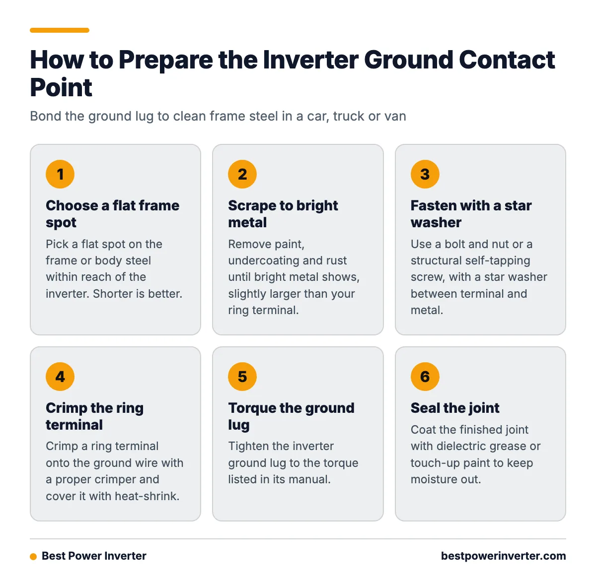
How to prepare the contact point
- Choose a flat spot on the frame or body steel within reach of the inverter.
- Scrape or grind away paint, undercoating and rust until you see bright metal, slightly larger than your ring terminal.
- Drill and use a bolt with a nut, or a self-tapping screw rated for structural use. Add a star washer between the terminal and the metal so it bites in.
- Crimp a ring terminal onto the ground wire with a proper crimper and cover it with heat-shrink.
- Tighten the inverter’s ground lug to the torque in its manual.
- Coat the finished joint with dielectric grease or touch-up paint to keep moisture out.
What size wire should I use for the inverter ground?
Use the gauge the inverter manual lists, and never go smaller. Many manuals specify a chassis ground conductor of 8 AWG or larger. AWG stands for American Wire Gauge, where a smaller number means a thicker wire. If the manual gives a minimum, treat it as a floor. Going one size thicker costs little and adds margin.

Worked example
A pickup owner installs a 2000W pure sine inverter on a 12V battery to run job-site tools.
Step 1: DC current. Watts ÷ volts ÷ efficiency. 2000 ÷ 12 ÷ 0.9 = about 185A at full load.
Step 2: DC fuse. A common rule for continuous loads is to size the fuse at 125% of the expected current. 185 × 1.25 = about 231A, so the next standard size up is a 250A fuse. Mount it within 7 inches (about 18 cm) of the battery positive post.
Step 3: DC cable. The positive and negative cables must be rated above the 250A fuse for their length. Use the cable table in the inverter manual, and keep the run as short as possible to limit voltage drop.
Step 4: Ground wire. The manual lists 8 AWG minimum. The owner runs 8 AWG green wire, 18 inches long, from the ground lug to a scraped spot on the frame rail under the rear seat, with a star washer and ring terminal.
Step 5: Check. With the inverter on, a plug-in outlet tester shows correct wiring, which confirms the internal neutral-ground bond and the chassis ground are both working.
How do I ground an inverter in an RV or camper van with shore power?
Bond the ground lug to the RV chassis, then make sure the neutral-ground bond switches off whenever shore power is plugged in. That second part is where most RV installs go wrong.
Under NEC Article 551, the RV’s own distribution panel keeps neutral and ground separate. The bond happens at the campground pedestal or the house service. When you run on the inverter alone, the inverter becomes the power source, so it needs to supply that bond. When shore power returns, the inverter must remove its bond, or you end up with two bonds on one system.
Inverter-chargers built for RVs handle this with an internal transfer relay. The Magnum CSW1012 owner’s manual is a good example of how such a unit describes its transfer and grounding connections. If you use a plain portable inverter with an external transfer switch, check whether the inverter bonds neutral internally. If it does, the transfer switch must also switch the neutral, or you should choose an inverter designed for panel connection.
Grounding an inverter on a boat
Boats follow ABYC standards, not the NEC. ABYC E-11 covers AC and DC electrical systems on boats, and ABYC A-31 covers battery chargers and inverters. E-11 calls for the AC grounding system to connect to the boat’s DC negative ground, typically at the main negative bus or engine negative terminal, so a fault on either side has a return path.
Water adds a second problem: galvanic corrosion. When your boat’s AC ground is tied to shore ground through the dock cable, underwater metals on your boat and neighboring boats can form a weak battery through the water. That slowly eats zincs, props and through-hulls. A galvanic isolator or isolation transformer on the shore power side blocks that current while keeping the safety ground intact. As with RVs, the inverter must bond neutral to ground only while it is the source, and drop that bond on shore power.
How is a 48V off-grid or home inverter grounded differently from a 12V vehicle inverter?
A fixed 48V system has no chassis to bond to, so the inverter’s ground lug goes to the building’s grounding electrode system. That is usually a ground rod or the existing electrode at the service. All equipment grounds, including the battery rack, inverter case and charge controller, tie into a single grounding busbar that connects to the electrode.
Fixed installs fall under NEC Article 250 for grounding and bonding, and Article 690 for solar PV systems. Many off-grid designs also bond the DC negative to the grounding system at one point. Whether yours must depends on the inverter manual and the code edition your inspector enforces. This overview of PV systems and the NEC walks through how Article 690 handles system and equipment grounding.
Voltage also changes the current. The same 2000W load that pulls about 185A on 12V draws only about 46A on 48V. Thinner DC cables and smaller fuses become practical, but the grounding still has to be done to code, and most areas require a permit and inspection for a fixed install.
What is neutral-to-ground bonding, and does my inverter already do it?
Neutral-to-ground bonding is a single connection between the AC neutral wire and the ground wire. It gives fault current a path back to the source so breakers trip. The NEC requires that bond at exactly one point in a system.
Most portable inverters with outlets on the front bond neutral to ground internally. That is correct when you plug loads straight into the inverter. Problems start when the same inverter is hardwired into an RV panel or house subpanel. Here is how the three common setups compare:
Correct: one bond. The inverter bonds while inverting, the panel keeps neutral and ground separate, and shore or utility power provides the bond when connected. Fault current returns to one source, and GFCIs work.
Wrong, double bond: the inverter bonds internally and the house or shore service also bonds. Normal neutral current now splits onto the ground wires and metal parts. GFCIs trip at random, and ground conductors carry current they should never carry.
Wrong, floating neutral: the inverter does not bond, and the transfer switch has removed the shore bond. A hot-to-case fault has no clean return path, so breakers may not trip, and outlet testers report an open ground.
Wrong, ground lug unconnected: the bond inside the inverter exists, but the case and frame are not tied together. A fault can leave the frame or nearby metal at a different voltage from the inverter case.
Why does my GFCI outlet trip or not work on my inverter?
The usual causes are a modified sine wave output, a floating neutral, or a double bond. A GFCI compares current on the hot and neutral wires and trips when they differ, which means some current is leaking elsewhere.
- Modified sine inverters: their stepped waveform has sharp edges that can confuse the GFCI’s sensing electronics. The result is nuisance tripping or an outlet that will not reset. A pure sine inverter is the reliable fix.
- Floating neutral: the GFCI’s own test button may still work, because it creates an internal imbalance. But a plug-in tester with a GFCI button leaks current to ground, and with no bond there is nowhere for it to go, so the test fails.
- Double bond: neutral current spreads onto ground paths, the GFCI sees an imbalance, and it trips under normal loads.
Does grounding change with inverter size, for example 2000W versus 4000W?
The ground wire gauge comes from the manual, but bigger inverters raise the stakes on everything around it. Current climbs fast on low-voltage systems. Using watts ÷ volts ÷ 0.9 efficiency:
| Inverter size | 12V draw | 24V draw | 48V draw |
|---|---|---|---|
| 1000W | about 93A | about 46A | about 23A |
| 2000W | about 185A | about 93A | about 46A |
| 3000W | about 278A | about 139A | about 69A |
| 4000W | about 370A | about 185A | about 93A |
At 300A or more, a loose lug or a painted ground point can heat up quickly during a fault, and the DC fuse has to be big and close to the battery. That is why high-wattage systems usually move to 24V or 48V. If you want 3000W or more, a higher battery voltage is the better choice for most readers.
Can a bad ground cause inverter faults, humming TVs, or printer and electronics problems?
Yes, a poor or missing ground can cause several of these symptoms, though not all of them.
- Tingling from the case or metal nearby: the ground lug is loose, corroded or unconnected. Shut the inverter off and fix it before using it again.
- Hum in a TV or audio system: often a ground loop, where the gear is grounded through two paths, such as the inverter and a cable or antenna line. A double neutral-ground bond can also cause it. A steady buzz in speakers on a modified sine inverter is usually the waveform, not the ground.
- Printer or electronics errors: laser printers and devices with switching power supplies can misbehave on modified sine output. Check the waveform before blaming the ground.
- Inverter fault codes or random shutdowns: check the DC connections first. A loose negative cable causes voltage drops that trigger low-voltage alarms.
- GFCI tripping: see the section above. Look for a double bond first.

Pre-power-on checklist and when to hire an electrician
Run through this list before the first power-up, and again after any wiring change.
- Ground lug tightened to the manual’s torque value.
- Paint, rust and undercoating removed at the chassis contact; star washer in place.
- Ground wire at or above the manufacturer’s minimum gauge.
- DC fuse installed within 7 inches (about 18 cm) of the battery positive.
- DC cables rated above the fuse size and kept short.
- Single neutral-ground bond confirmed: inverter only, or panel only, never both.
- Plug-in GFCI tester result recorded at the first outlet.
- For RV or boat: bond confirmed to drop when shore power connects.
Hire a licensed electrician for any inverter wired into a house panel, any fixed 48V off-grid system, and any install that needs a permit. A marine technician familiar with ABYC is the right call for boats. A plug-in inverter bolted into a truck is a fair DIY job. Hardwiring into a building is not.
Frequently Asked Questions
How big of a power inverter can my truck handle?
It depends on your battery and alternator, not the truck itself. A cigarette lighter socket is commonly fused at 15 to 20 amps, which limits you to roughly 150 to 200W. Anything larger must be wired straight to the battery with a fuse near the post. For running loads while driving, keep the inverter’s draw below what the alternator can supply after the truck’s own needs.
How big of power inverter for 12v car?
Add up the watts of what you will run at once, then add margin for starting surge. Small loads like laptops and phone chargers run fine through a socket-powered unit. Above a few hundred watts, wire it to the battery and ground the case to the chassis as described above.
4000 watt power inverter: can I run it on 12V?
You can, but it can draw over 370A at full load. That needs very heavy cables, a large fuse close to the battery, and a strong battery bank. Most people building a 4000W system are better off at 24V or 48V.
48 volt power inverter: how is it grounded?
The case goes to the building’s grounding electrode system through a grounding busbar, under NEC Articles 250 and 690. Make sure the neutral-ground bond happens in only one place, and have the install inspected.
How big of a power drain is an inverter?
Under load, it draws roughly AC watts ÷ battery voltage ÷ efficiency. A 2000W load on 12V at 90% efficiency pulls about 185A. Inverters also draw a small idle current when switched on with nothing plugged in. Check the spec sheet for that figure and turn the inverter off when not in use.
How big power inverter to run sump pump?
Check the pump’s label for running watts, then allow for a starting surge several times higher, since motors pull extra current at start-up. Choose a pure sine inverter whose surge rating covers that start, and if it feeds a house circuit, have the transfer switch and bonding set up by an electrician.
Sources