
A DIY power inverter changes 12V DC battery power into 120V AC power that small household devices can use. You can build a basic one with an oscillator chip, a few MOSFETs, and a step-up transformer. It works best for small loads under 300 watts, and it demands respect because the output can kill.
- A simple DIY inverter uses a CD4047 oscillator, power MOSFETs, and a center-tapped transformer run backward.
- Expect a modified square wave output, not a pure sine wave. It suits lights, chargers, and simple tools.
- Keep loads under 300W. At that power, a 12V system pulls about 25 to 30 amps.
- Fuse the battery line within 7 inches of the positive post.
- Do not power CPAP machines, sensitive electronics, or medical gear with a homemade unit.

What a DIY Power Inverter Can and Cannot Do
An inverter has one job. It takes DC from a battery and makes AC. The circuit flips the battery voltage back and forth 60 times each second. A transformer then raises the voltage from 12V to about 120V.
That sounds simple. It is, at small scale. A homemade unit can run LED lights, a phone charger, a laptop brick, or a small fan. It struggles with anything that has a big motor or a delicate power supply.
Here is the honest range. Most hobby builds land between 100W and 300W. Push past that and the wire gets thick, the heat sink gets big, and the risk goes up fast. At that point, a store-bought unit is usually cheaper and safer.
How We Evaluated This
We judged each design choice against six criteria. Every part and step in this guide had to pass them.
- Safety: Does it limit fire and shock risk? Fuses, cutoffs, and enclosures count here.
- Parts availability: Can a beginner buy everything from common electronics suppliers?
- Efficiency: How much battery power turns into useful output? A simple design often reaches 70 to 85 percent.
- Heat management: MOSFETs and transformers both run hot under load.
- Cost-to-performance: Is the build cheaper than a retail unit of the same size?
- Output quality: Will the waveform harm common devices?
Reference material included the CD4047 datasheet, MOSFET ratings, and standards such as UL 458, which covers power converters for mobile use. A homemade build will not carry that listing. We used the standard as a checklist for good practice, not as a claim of compliance. This guide was reviewed against current practice as of September 2026.
Inverter Output Types Explained
Not all AC is equal. The shape of the wave matters for what you can plug in.

Square Wave
The simplest type. The voltage jumps between positive and negative. It is cheap to build. It is also hard on motors and can cause buzzing in audio gear.
Modified Sine Wave
This adds a short pause at zero volts between each flip. The result is a stepped wave that is closer to household power. Most DIY circuits with a CD4047 produce a wave in this family, though a basic build is closer to a square wave than a true modified sine.
Pure Sine Wave
This matches utility power. It needs a more complex design, often with SPWM control and filter parts. Pure sine is the right choice for CPAP machines, variable-speed tools, and audio gear. You can read more about how these waveforms work in this overview of power inverters.
Parts List
This list fits a 150W to 300W build. Quantities assume a push-pull design.
- CD4047 oscillator IC: Sets the 60Hz switching rate.
- Four IRF3205 N-channel MOSFETs: Two per side of the push-pull stage. They handle up to 110A on paper, but real limits depend on heat.
- Center-tapped transformer, 12-0-12V: Rated at least 25A on the low side. You will run it in reverse, so the 120V winding becomes the output.
- Heat sinks with thermal paste and insulating pads: The MOSFET tabs are electrically live.
- Gate resistors, about 100 ohms: They protect the CD4047 outputs.
- Timing parts: A 0.1 microfarad capacitor, a 33k ohm resistor, and a 10k trim pot.
- Fuse and holder: A 40A automotive blade or ANL fuse for a 300W design.
- 10 AWG copper wire: For short battery runs under 3 feet.
- 12V deep cycle battery: At least 35Ah for useful runtime.
- Insulated project enclosure with vents: Plastic or coated metal.
Why the Transformer Matters Most
The transformer is the heart and the biggest cost. A cheap unit sags under load and runs hot. Check the wire gauge on the low-voltage side. If the primary leads look thin, the rating is likely inflated.

Step-by-Step Build
Work on a dry bench. Keep the battery disconnected until the final test.
Step 1: Set the Frequency
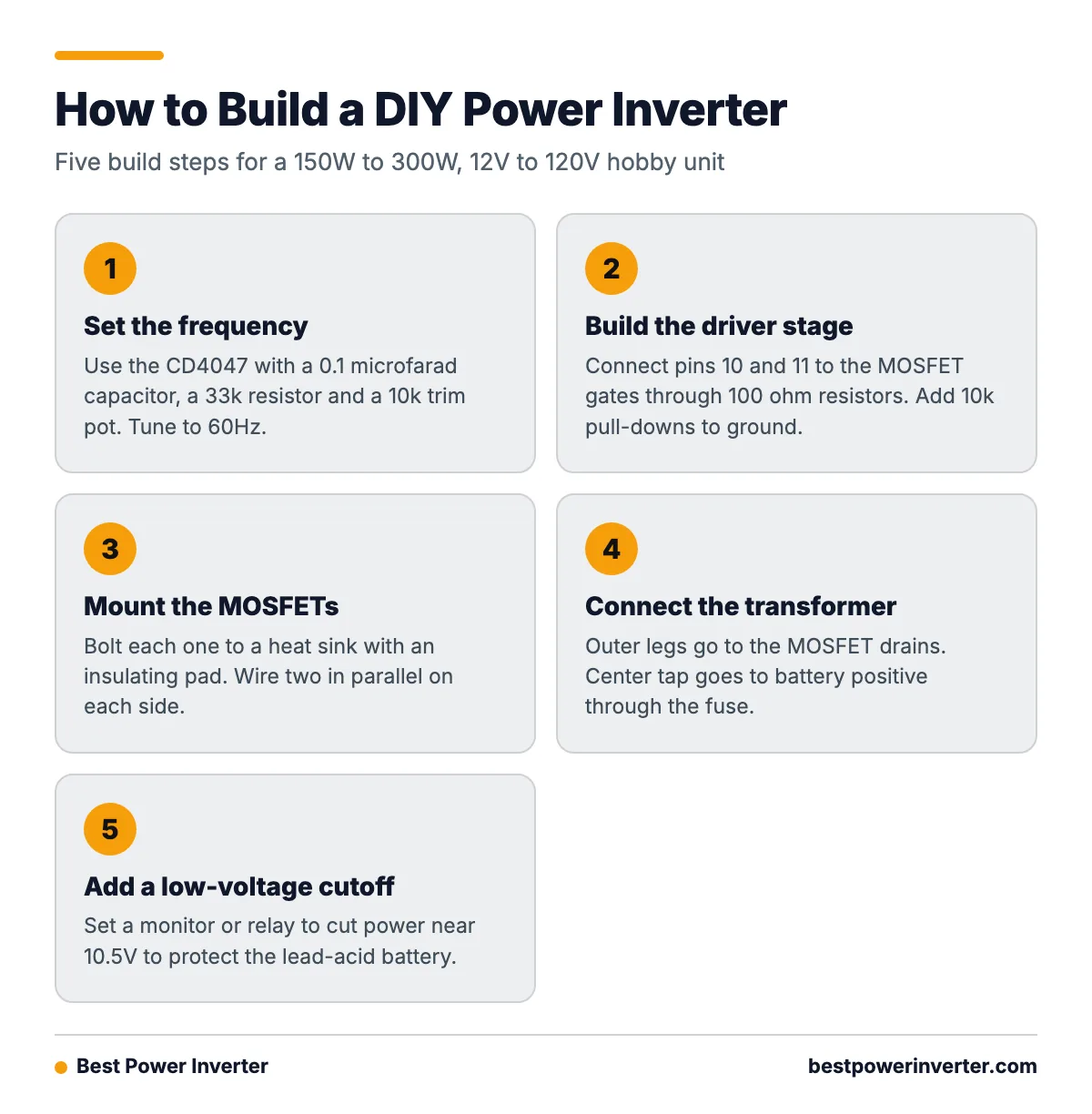
The CD4047 in astable mode outputs at roughly 1 divided by (4.4 x R x C). For 60Hz with a 0.1 microfarad capacitor, you need about 38k ohms. Use a 33k resistor in series with a 10k trim pot so you can tune it. Aim for 60Hz on a frequency counter or a multimeter with Hz mode.
Step 2: Build the Driver Stage
Connect the two opposite outputs of the CD4047 (pins 10 and 11) to the MOSFET gates through 100 ohm resistors. Add a 10k pull-down resistor from each gate to ground. This keeps the MOSFETs off during startup.
Step 3: Mount the MOSFETs
Bolt each MOSFET to the heat sink with an insulating pad. Put two on each side of the push-pull pair, wired in parallel. Paralleling shares the current and lowers heat.
Step 4: Connect the Transformer
Wire the outer legs of the 12-0-12 winding to the drains of each MOSFET pair. Wire the center tap to battery positive through the fuse. Connect all MOSFET sources to battery negative. The high-voltage winding is now your AC output.
From the Shop
The most common failure we see on first builds is a burned MOSFET pair within seconds of power-up. The cause is nearly always the same. The gates float during startup, both sides switch on at once, and the transformer becomes a dead short. Pull-down resistors and a fuse stop that. Skip both and the parts cost adds up quickly.
Step 5: Add a Low-Voltage Cutoff
A lead-acid battery drops in life if you drain it below about 10.5V. Add a simple voltage monitor or relay module set to cut power near that level. This protects the battery and keeps the MOSFETs from running in a weak-drive state.
Wiring, Fusing, and Safety
This is the part that matters most. Two hazards exist. The battery side carries high current. The output side carries lethal voltage.
Battery Side
A 12V battery can deliver hundreds of amps in a short circuit. A dropped wrench can weld itself to a terminal. Place the fuse within 7 inches of the positive post. Use ring terminals, crimped and soldered, not clips. Size wire for the amps, plus a margin. At 25 to 30 amps and under 3 feet, 10 AWG is a fair minimum. Longer runs need thicker wire to limit voltage drop.
Output Side
Treat the 120V winding as live any time the battery is connected. Enclose it. Keep all exposed terminals covered. Use a grounded outlet only if you bond the case properly, and add a GFCI outlet strip on the output for extra protection. The OSHA electrical safety page explains why even small AC currents can cause serious injury.
Heat and Ventilation
MOSFETs lose power as heat. At 300W, expect 30 to 60W of waste heat. Use a heat sink with fins and add a small 12V fan if the case is closed. Drill vent holes above and below the heat sink. If the heat sink is too hot to touch for more than a couple of seconds, cut the load.
Testing and Troubleshooting
Start small. Use a 12V bulb or a lamp in series as a current limiter for the first power-up. If the bulb glows dim, the circuit draws little. If it glows bright, you have a short.
- Check that the oscillator reads 60Hz with no load.
- Connect the battery through the fuse. Measure the output with a true-RMS meter. A basic build may read 110 to 140V depending on battery voltage.
- Add a 25W incandescent bulb. Watch the heat sink temperature.
- Step up to 100W, then 200W. Stop if anything smells hot.
Common Failure Points
- Blown MOSFETs: Usually caused by floating gates, shorts, or poor heat sinking.
- Weak output: Often a tired battery, thin wire, or an undersized transformer.
- Loud hum: The frequency may be off, or the transformer core is saturating.
- Battery drains fast: Idle draw from a cheap transformer can hit 1 to 2 amps.
- If the fuse blows on power-up, check for a shorted MOSFET or floating gates.
- If the output voltage is low, check battery charge and wire gauge first.
- If the heat sink runs too hot, reduce the load or add a fan.
- If a device buzzes or resets, it needs a cleaner waveform. Use a pure sine unit.

DIY or Buy: Which Is Right?
A DIY inverter teaches you a lot about switching circuits, transformers, and heat. It is a good learning project. It is not always a good money saver.
A store-bought 300W modified sine inverter often costs less than the parts for a quality build. A pure sine model in the same size costs more, but it comes with overload, over-temperature, and low-battery protection built in. Many also carry UL 458 or similar listings.
- You want to learn how inverters work.
- Your load is small, simple, and not critical.
- You can test with a meter and know basic electrical safety.
Buy a ready-made unit if:
- You need to run medical gear, a fridge, or power tools.
- You need more than 300W.
- The inverter will stay in a vehicle, boat, or home.
One last point. Insurance and local code may not cover a homemade device wired into a building. Keep DIY units portable, and never connect one to your home wiring. That can send power back into the grid and put line workers at risk.
Frequently Asked Questions
Can I build a DIY power inverter for my whole house?
No. Whole-home inverters need certified parts, proper transfer switches, and often a permit. A homemade unit is only safe for small, plug-in loads.
How much power can a DIY inverter handle?
Most hobby builds top out around 300W. Larger loads need very thick wire, big heat sinks, and heavier transformers. Cost and risk both climb quickly past that point.
Is a DIY inverter pure sine wave?
Usually not. Simple CD4047 designs produce a square or modified wave. A pure sine design needs SPWM control and output filtering, which is a much harder build.
What size battery do I need?
Divide the load in watts by 12 to get amps. A 120W load pulls about 10 amps, plus losses. A 35Ah battery would run that for roughly two hours if you only use about half its capacity, which is best for lead-acid.
Can I run a laptop or phone charger on it?
Usually yes. Most switch-mode chargers handle a modified wave. Start with a short test and check that the charger does not run unusually hot.
Why does my inverter blow fuses?
The most common causes are a shorted MOSFET, floating gate signals at startup, reversed battery polarity, or a load that is too big. Check each one before you replace the fuse with a larger one. A bigger fuse hides the problem and adds fire risk.
Is it legal to build my own inverter?
In most places, yes, for personal use. Selling one or wiring one into a building often requires certification and inspection. Check local rules before you go beyond a portable hobby unit.