
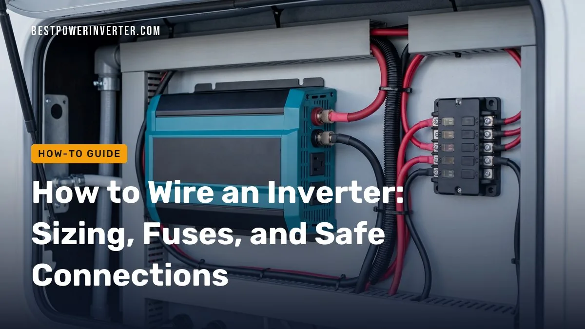
Wiring an inverter requires correctly sized positive and negative DC cables, a properly rated fuse mounted near the battery, and tight, polarity-correct connections. The cable thickness and fuse size you need depend entirely on your inverter’s maximum wattage, the battery bank’s voltage, and the length of the cable run. Small portable units might plug directly into a socket, but permanent home backup systems demand heavy-gauge wiring and strict safety protocols to prevent overheating.
Quick answer
To safely wire an inverter, run heavy-duty copper cables from the battery bank to the inverter’s DC terminals, matching positive to positive and negative to negative. You must install a catastrophic fuse or circuit breaker on the positive cable close to the battery. Always consult your inverter’s manual for specific cable gauge requirements, and hire a licensed electrician to connect the inverter’s AC output to your home’s main electrical panel.
- DC cable sizes and fuse ratings must match the inverter’s power rating and battery voltage.
- The main safety fuse must sit on the positive cable, typically within 18 inches of the battery terminal.
- Higher voltage systems (like 48V) allow for much thinner cables compared to 12V systems.
- Sump pumps and appliances with electric motors require an inverter sized for peak startup surge, not just running watts.
- Connecting an inverter to a home electrical panel requires a manual transfer switch to isolate utility power.
- What is inverter wiring?
- How is inverter wiring done from the battery to the inverter?
- Which wire is used to connect an inverter and battery?
- 12V, 24V, and 48V Inverter Systems Compared
- How do I install an inverter safely for a home circuit?
- How large must a power inverter be to run a sump pump?
- Does installing an inverter increase the electricity bill?
- Why is my inverter connection not working?
- Frequently Asked Questions
What is inverter wiring?
Inverter wiring bridges the gap between stored battery power and your household appliances. It consists of two distinct sides: the DC (Direct Current) input and the AC (Alternating Current) output. The DC side connects your battery bank to the inverter. This side carries high current at low voltage. The AC side distributes the converted power to your electronics, operating at standard household voltages (110V or 230V) with much lower current.
Most installation errors occur on the DC side. Because batteries output low voltage, pushing high wattage requires massive amounts of electrical current (amps). Thin wires cannot handle this flow. They heat up rapidly. Proper inverter wiring manages this heat through thick copper cables, tight connections, and strict overcurrent protection.
How is inverter wiring done from the battery to the inverter?
Installing an inverter means creating a closed, protected DC loop between the power source and the unit. You start by mounting the inverter in a cool, dry, well-ventilated space close to the batteries to keep cable runs as short as possible.
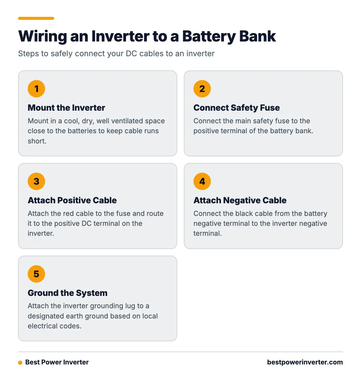
First, connect the main safety fuse to the positive terminal of the battery bank. Next, attach the positive (red) cable to the fuse, routing it to the positive DC terminal on the inverter. Then, connect the negative (black) cable from the battery bank’s negative terminal to the inverter’s negative terminal. Finally, attach the inverter’s grounding lug to a designated earth ground according to local electrical codes.
Never skip the fuse. Victron’s DC wiring guidelines clearly state that each individual DC consumer needs its own dedicated fuse. Without one, a shorted cable can pull thousands of amps from a battery bank instantly, melting the insulation and starting a severe fire.

Which wire is used to connect an inverter and battery?
You must use stranded copper wire to connect an inverter and battery. Stranded wire bends easily and carries high DC currents effectively. Solid core wire is strictly for AC household circuits and will break if used for battery connections.
Cable thickness (gauge) is dictated by your inverter’s wattage, the battery voltage, and the total length of the cable. Longer distances cause a drop in voltage. If the voltage drops too low before reaching the inverter, the unit will trigger a low-voltage alarm and shut down. To compensate for long runs, you must increase the cable thickness.
From the Shop
We often see DIY setups fail simply because the battery cables are too thin. A user might buy a 3000W inverter and wire it using standard jumper cables. When they turn on a microwave, the massive amp draw chokes at the thin wire, the voltage drops to 10V, and the inverter screeches an error code. Upgrading to heavy 4/0 AWG copper wire immediately solves the false shutdown.
12V, 24V, and 48V Inverter Systems Compared
What is a 48-volt power inverter, and when is it better than a 12-volt model? A 48V inverter requires a battery bank wired to output 48 volts. Higher voltage drastically reduces the amount of current (amps) needed to produce the same amount of power (watts). Less current means you can use thinner, cheaper cables and smaller fuses.
Let’s look at the math. A system supplying 1000W from a 12V battery ideally draws approximately 83.3 amps (1000 ÷ 12). Allowing for natural inverter conversion losses, the actual current is even higher. In contrast, a 48V system supplying that same 1000W ideally draws only 20.8 amps (1000 ÷ 48).
This difference completely changes the hardware required. Based on Victron Energy’s installation data for their 1600W inverters, the wire and fuse requirements change heavily based on system voltage:
| Victron 1600W Inverter | Required Cable Size (0-5 meters) | Required Fuse Rating |
|---|---|---|
| 12V Model | 70 mm² (approx. 2/0 AWG) | 250 Amps |
| 48V Model | 16 mm² (approx. 6 AWG) | 60 Amps |
A 12V system is perfect for small setups like camper vans or basic emergency backups. However, if you are building an off-grid home or running heavy loads like well pumps and air conditioners, a 48V system is far superior. It keeps wire costs down, runs cooler, and operates more efficiently.
How do I install an inverter safely for a home circuit?
Does an inverter need separate wiring or a dedicated home circuit? That depends entirely on how you plan to use it. If you have a small portable inverter, you can simply plug a lamp or a TV directly into the AC outlets on the front of the unit. In this case, no home wiring is involved.
However, if you want your inverter to power your home’s existing wall outlets and ceiling lights, it absolutely needs separate wiring managed by a transfer switch. You cannot plug an inverter into a wall outlet to “backfeed” your home. This is highly illegal, deadly to utility workers, and will destroy the inverter the moment grid power returns.
To safely wire an inverter into a home, an electrician installs a manual transfer switch next to your main breaker panel. The inverter’s AC output is hardwired into this switch. During a blackout, you flip the switch. This disconnects your home from the utility grid and reconnects your chosen circuits to the inverter. The systems remain entirely separate.
How large must a power inverter be to run a sump pump?
Sizing an inverter for a sump pump is a common hurdle because electric motors require a massive burst of power to start turning. This is called the startup surge, or Locked Rotor Amps (LRA). A pump that requires 800 watts to run might demand 2,500 watts for a split second when it kicks on.
If you size your inverter based only on the running watts, the pump will not start. The inverter will overload and shut down instantly. To size an inverter for a sump pump, you must calculate the exact startup surge.
- If the pump’s manual lists a surge wattage: Choose an inverter with a continuous rating slightly higher than the pump’s surge requirement.
- If the pump only lists Amps and Volts: Multiply Amps by Volts to get running watts (e.g., 7A x 120V = 840W). Then multiply running watts by 3 to estimate the startup surge (840W x 3 = 2,520W). You will need a 3000W inverter to be safe.
- If you want an exact figure: Use a clamp-on digital ammeter with an “inrush” feature on the pump’s power cord. Read the peak amps, multiply by 120 volts, and size your inverter accordingly.
Never rely on guesswork for critical equipment like sump pumps. Always err on the side of a larger inverter to ensure the motor starts cleanly without causing a heavy voltage dip.

Does installing an inverter increase the electricity bill?
An inverter connected to a battery bank does not directly interact with your utility bill while running off-grid. However, if you charge those batteries using grid power (via a battery charger), you will pay for the electricity it takes to recharge them. How much power an inverter consumes depends on conversion losses and standby draw.
Inverters are not 100% efficient. Converting DC battery power to AC household power usually results in a 10% to 15% energy loss, which burns off as heat. Furthermore, an inverter consumes power just by being turned on, even if nothing is plugged in. This is called the standby draw. A typical 2000W inverter might burn 15 to 30 watts continuously in standby mode. Over a 24-hour period, that phantom draw can drain a small battery bank entirely. If you want to conserve battery capacity, always turn the inverter off when not in use.
Why is my inverter connection not working?
When an inverter fails to turn on or continuously trips an alarm, the problem usually stems from a flaw in the DC wiring. The inverter’s internal computer protects the unit by shutting down if it detects unsafe conditions.
Check these common failure points:
- Loose connections: A loose nut on a battery terminal creates high resistance. Resistance drops the voltage. Use a wrench to ensure all DC connections are tight and secure.
- Reversed polarity: If you wire the positive cable to the negative terminal, most quality inverters will blow their internal fuses to protect the main circuit board. You must replace the fuses and correct the wiring.
- Blown inline fuse: Use a multimeter to check for continuity across the main battery fuse. If the fuse is blown, the inverter receives no power.
- Low battery voltage: If the cables are too thin for the length of the run, the inverter experiences a voltage drop under load. Verify that your cable gauge matches the manufacturer’s specifications for the exact distance.
- Overloaded output: If you try to run an appliance that exceeds the inverter’s maximum wattage (or startup surge), the inverter will instantly shut off power to protect its AC circuitry.
Frequently Asked Questions
how inverter wiring is done?
Inverter wiring is done by connecting properly sized DC cables from the battery bank directly to the inverter. The positive cable must have a correctly rated inline fuse installed close to the battery. Connections must be tight and strictly match positive to positive and negative to negative to prevent short circuits.
how install inverter?
Install the inverter in a clean, dry, and well-ventilated space close to the battery bank. Mount it securely. Connect the grounding lug to a proper earth ground. Attach the negative battery cable, then attach the fused positive battery cable. Finally, plug in your appliances or connect the AC output to a transfer switch.
how to wiring inverter in home?
To wire an inverter to run your home’s existing wall outlets, you must install a manual transfer switch beside your main breaker panel. The inverter connects to the transfer switch, completely isolating the backup system from the utility grid. A licensed electrician should perform this work to comply with local safety codes.
what is inverter wiring?
Inverter wiring refers to the heavy-duty direct current (DC) cables that transfer power from a battery to the inverter, and the alternating current (AC) wires that distribute the converted power to your appliances. Safe wiring manages high currents on the DC side using thick copper cables and strict fuse protection.
which wire is used in inverter?
For the battery connection, you must use high-quality stranded copper wire. The specific gauge required depends on the inverter’s wattage, the battery voltage, and the cable length. For the AC output side, standard household solid-core wiring (like 12/2 or 14/2 Romex) is typically used for hardwired connections.
which wire is used to connect inverter and battery?
Thick, stranded copper DC battery cables are used to connect the inverter to the battery. For example, a 1600W inverter running on a 12V battery usually requires at least 70 mm² (around 2/0 AWG) wire for a short run. A 48V system of the same size requires much thinner wire, such as 16 mm² (around 6 AWG).
why inverter connection is not working?
An inverter connection usually fails because the DC battery cables are too thin, causing a voltage drop that triggers an automatic shutdown. Other common reasons include a blown inline fuse, loose battery terminal connections, a drained battery bank, or an appliance drawing a startup surge larger than the inverter can handle.
do we need separate wiring for inverter?
Yes, if you intend to power built-in household lights and outlets. You cannot plug an inverter into a regular wall outlet. You need separate AC wiring routed through an approved transfer switch to isolate your inverter from the utility grid.
does inverter need separate wiring?
For standalone or portable use, no separate wiring is needed,you just plug devices directly into the inverter. However, connecting an inverter to a home electrical panel requires separate wiring and a dedicated transfer switch to safely manage the electrical loads without backfeeding the grid.
Sources