
Most people wire an inverter with cable that is too thin and a fuse that sits too far from the battery. The fix is simple: run short, thick copper cable from the battery positive through a fuse or breaker mounted close to the battery, then to the inverter, and run the negative straight back to the battery negative. If you want to power house circuits, you also need a transfer switch or interlock, never a back-feed through an outlet.
Quick answer
Connect inverter positive (red) to battery positive through a fuse or breaker within about 7 inches (18 cm) of the battery. Connect inverter negative (black) straight to battery negative. Use short, thick copper cable sized for the inverter’s full DC current, and follow the manual. For house circuits, use a transfer switch or interlock installed by a licensed electrician.
- Fuse the positive cable close to the battery. It protects the cable, not the inverter.
- DC amps equal watts divided by battery volts, divided by efficiency (about 0.85 to 0.9).
- A 2000W 12V inverter can pull roughly 175 to 195 amps. That needs 4/0 AWG on most installs.
- Connect the fuse or breaker last. Inverter capacitors cause a spark on first contact.
- Doubling system voltage halves the current. 24V and 48V allow thinner cable.
- Never back-feed a house panel through an outlet. Use a transfer switch or interlock.
- What Should a Power Inverter Wiring Diagram Show?
- What Parts Do You Need?
- How Do You Work Out the Amps, Cable and Fuse?
- Which Wire Is Used to Connect Inverter and Battery?
- What Size Fuse Do You Need and Where Does It Go?
- In What Order Do You Connect the Cables?
- How Do You Wire a 12V to 240V Inverter?
- How Do You Wire Multiple Batteries to an Inverter?
- Do You Need to Ground the Inverter?
- How to Wire an Inverter to Your House
- Common Wiring Mistakes
- Frequently Asked Questions
What Should a Power Inverter Wiring Diagram Show?
A good power inverter wiring diagram shows one path for current out of the battery and one path back. The positive path has a fuse and a disconnect. The negative path is short and direct. The AC side leaves the inverter and goes to your loads.
BATTERY (+) --[Fuse / breaker, within 7 in]--[Disconnect switch]-- INVERTER (+)
BATTERY (-) --------------[Shunt, optional]------------------- INVERTER (-)
INVERTER chassis lug ------------------------------------------ Ground / chassis
INVERTER AC out ----[AC breaker or transfer switch]------------- Outlets / loads
Many diagrams online skip the fuse position. That is the part that matters most. If a cable shorts to metal between the battery and the fuse, nothing protects it. So the fuse goes on the positive cable as close to the battery as you can mount it. Marine guidance such as ABYC commonly puts that at about 7 inches (18 cm).
What Parts Do You Need?
Here is the full parts list for a basic power inverter wiring diagram with battery:
- Battery or bank: sized for the load and the inverter’s peak draw.
- Two DC cables: fine-strand copper, red and black, same gauge.
- Fuse or DC breaker: rated for DC, with a high enough interrupt rating.
- Fuse holder or breaker mount: bolted down, not hanging on the cable.
- Disconnect switch: lets you isolate the inverter for service.
- Lugs: tinned copper, crimped with a hydraulic or hammer crimper, then sealed with heat-shrink.
- Busbars: useful when several loads share one battery.
- Ground wire: sized per the manual.
Skip cheap clamp-style lugs and thin crimps. A loose lug at 200 amps turns into a heater.
How Do You Work Out the Amps, Cable and Fuse?
Start with watts, convert to DC amps, then pick the fuse and cable. The formula is: DC amps = inverter watts ÷ battery volts ÷ efficiency. Most inverters run at about 85 to 90 percent efficiency, so use 0.85 to stay safe.
Worked example: 2000W, 12V inverter
- Ideal current: 2000 ÷ 12 = 167 amps.
- Add losses: 167 ÷ 0.85 = about 196 amps. At 0.9 efficiency it is about 185 amps.
- Fuse: 196 × 1.25 = 245. Round to a 250A fuse or breaker.
- Cable: 4/0 AWG copper. It can carry the 250A fuse rating with margin.
- Check the drop: with 5 ft each way (10 ft round trip), 4/0 has about 0.00049 ohms. 196 A × 0.00049 = 0.096 V. That is under 1 percent of 12V.
Some manuals allow 2/0 on very short runs for a 2000W unit. Use the manual’s number if it is larger than mine. Never go smaller.

Which Wire Is Used to Connect Inverter and Battery?
Use fine-strand (flexible) copper welding or battery cable, in matching red and black. Do not use aluminum or copper-clad aluminum. Gauge depends on current, run length and allowed voltage drop.
The table below uses the formula above at 85% efficiency. It assumes copper cable, round-trip length (positive plus negative), and 3% voltage drop at nominal voltage. Lengths are one way, battery to inverter. These are calculated values, not lab results. Always check your inverter manual.
| System | Inverter | DC amps | Fuse | Copper cable | Max one-way length (≤3% drop) |
|---|---|---|---|---|---|
| 12V | 300W | 29 A | 40 A | 8 AWG | about 9 ft |
| 12V | 1000W | 98 A | 125 A | 2 AWG | about 11 ft |
| 12V | 2000W | 196 A | 250 A | 4/0 AWG | about 18 ft |
| 12V | 3000W | 294 A | 350 A | 4/0 AWG | about 12 ft |
| 24V | 300W | 15 A | 20 A | 10 AWG | about 24 ft |
| 24V | 1000W | 49 A | 60 A | 6 AWG | about 18 ft |
| 24V | 2000W | 98 A | 125 A | 2 AWG | about 23 ft |
| 24V | 3000W | 147 A | 200 A | 2/0 AWG | about 31 ft |
| 48V | 300W | 7 A | 10 A | 12 AWG | about 61 ft |
| 48V | 1000W | 25 A | 30 A | 10 AWG | about 29 ft |
| 48V | 2000W | 49 A | 60 A | 6 AWG | about 37 ft |
| 48V | 3000W | 74 A | 100 A | 2 AWG | about 62 ft |
A 3000W 12V inverter pulls close to 300 amps. Some builders use two parallel runs of 2/0 instead of one 4/0. Others move up to 24V. Need a longer run? Go up one or two cable sizes. Thicker cable is cheaper than a burned inverter. Victron’s Wiring Unlimited DC wiring chapter explains cable sizing and voltage drop in more depth.
What Size Fuse Do You Need and Where Does It Go?
Size the fuse about 125% of the inverter’s full-load DC current, then round up to the next standard size. The cable must be rated at or above that fuse. The fuse protects the cable from a short, so it goes on the positive cable within about 7 inches of the battery.
The type matters too. Lithium batteries can deliver a huge short-circuit current. A plain automotive blade fuse or a basic ANL may not break that safely. Class T fuses have a high interrupt rating and are the usual pick for lithium and large inverters. ANL fuses are common on lead-acid systems. A DC-rated breaker is fine if its interrupt rating suits your battery.
In What Order Do You Connect the Cables?
Connect the battery side first, the inverter side second, and the fuse or breaker last. The inverter has big capacitors inside. When they first see battery voltage, they pull a sudden surge of current. That makes a bright spark at the terminal. It is normal, but you want it at a switch or fuse, not at a loose cable end.
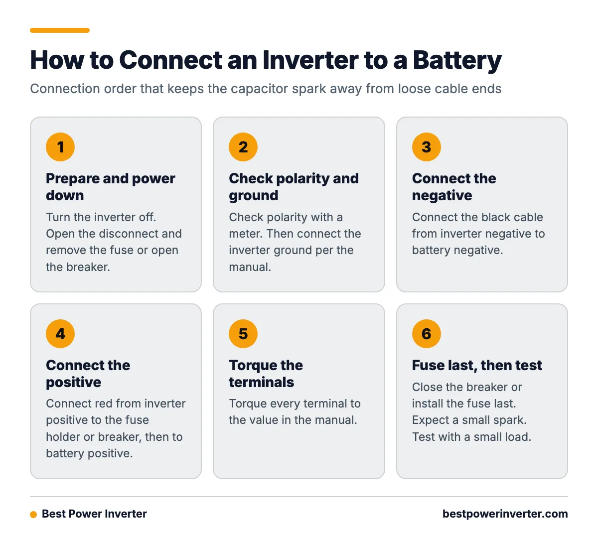
Connection order checklist
- Turn the inverter off. Open the disconnect and remove the fuse or open the breaker.
- Check polarity with a meter. Reversed polarity can destroy an inverter.
- Connect the inverter ground per the manual.
- Connect the black cable from inverter negative to battery negative.
- Connect the red cable from inverter positive to the fuse holder or breaker, then to battery positive.
- Torque every terminal to the manual’s value.
- Close the breaker or install the fuse last. Expect a small spark.
- Turn the inverter on and test with a small load.
To disconnect, reverse it: switch off, open the breaker or pull the fuse, then remove the cables. Some installers add a pre-charge resistor to charge the capacitors slowly. Follow the maker’s instructions on that. Victron’s Inverter Smart installation guide shows a typical manufacturer procedure.
Pre-installation checklist
- Inverter manual read, with cable and fuse specs noted.
- Cable length measured, round trip.
- Fuse type matched to battery chemistry.
- Mounting spot dry, ventilated, and away from fuel vapors.
- Tools ready: crimper, torque wrench, meter, heat-shrink.
How Do You Wire a 12V to 240V Inverter?
The DC side is wired the same way as any other inverter. Battery, fuse, cable and inverter, in the order above. The only change is the AC side: a 12V to 240V inverter puts out 230 or 240 volts, so the loads, breaker and plug must match that voltage.
In the US, household power is 120V, and many inverters output 120V. True 240V split-phase needs a split-phase inverter or two inverters set up together. Check the model’s output before you buy.
Here is what changes between system voltages:
- 12V: highest current. Heavy cable and big fuses. Best for small inverters and short runs.
- 24V: half the current of 12V for the same watts. A common choice at 2000W and up.
- 48V: a quarter of the 12V current. Thinner cable and long runs. Common in home backup and off-grid.
This is the reason big inverters tend to be 24V or 48V. Double the voltage, halve the amps, and the cable shrinks.
How Do You Wire Multiple Batteries to an Inverter?
Series wiring adds voltage. Two 12V batteries in series make 24V. Parallel wiring keeps voltage the same and adds capacity (amp-hours). Match the bank to your inverter’s input voltage.
- Series: connect positive of battery one to negative of battery two. Take the inverter leads from the two free terminals.
- Parallel: connect all positives together and all negatives together. Use cables of equal length and gauge.
For parallel banks, take the inverter positive from the first battery and the negative from the last one. This balances the current across the batteries. Use identical batteries of the same age, type and capacity. Mixing them causes uneven charging and early failure. Put the main fuse on the combined positive output, close to the bank, and add a fuse on each parallel string if the maker advises it.
Do You Need to Ground the Inverter?
Yes, in most cases. Inverters have a chassis ground lug, and the manual tells you where to connect it. In a vehicle or boat, that is usually the chassis or the DC grounding system. In a fixed home install, it goes to the building’s grounding electrode system per local code.
Neutral-to-ground bonding is a separate point. Some inverters bond neutral to ground inside, and some do so only when running off the battery. If you also have shore power, a generator or a transfer switch, a second bond can cause shock risk or trip protection. Read the manual and follow your local code. If you are unsure, hire an electrician.
How to Wire an Inverter to Your House
To wire an inverter to your house safely, connect it through a transfer switch or a panel interlock. Both stop your inverter from feeding power back out to the utility line. Have a licensed electrician install it, and pull any permit your area requires.
Back-feeding means plugging the inverter into a wall outlet with a male-to-male cord. Do not do this. Power can flow out to the grid and hurt utility workers. The cord also leaves exposed live prongs. In the US, NEC Article 702 and Article 705 require equipment that prevents backfeed. Many other countries have similar rules.

- Plug-in loads only (fridge, lights, laptop): run extension cords from the inverter’s own outlets. No house wiring needed.
- A few fixed circuits (well pump, furnace fan): use a manual transfer switch with a small backup sub-panel. The inverter feeds only those circuits.
- Many circuits through the main panel: use a listed interlock kit or an automatic transfer switch. Size the inverter for the loads you will run.
- Not sure, or a 240V load: stop and call an electrician.
A transfer switch moves selected circuits from the utility to the inverter, and it cannot connect both at once. An interlock is a mechanical plate on the main panel. It stops the main breaker and the inverter breaker from being on together. Both work when installed to code. Neither lets you run the whole house on a small inverter. Add up the watts first.
Common Wiring Mistakes
- Cable too thin or too long: causes voltage drop, low-voltage alarms and hot cable.
- No fuse, or the fuse far from the battery: a short in that stretch has no protection.
- Wrong fuse type: an ANL or blade fuse on a large lithium bank may not break a hard short.
- Poor crimps and loose lugs: they heat up under load and can start fires.
- Connecting the fuse first: the capacitor surge makes a big spark. Connect it last.
- Reversed polarity: can destroy the inverter instantly.
- Skipping the ground: leaves a shock path if there is a fault.
- Mismatched battery bank: uneven batteries cause low-voltage shutdowns.
- Back-feeding an outlet: dangerous and often illegal.
If your inverter trips a low-voltage alarm at moderate load, check voltage at the inverter terminals while it runs. A big gap between battery and inverter voltage points to cable or connection problems. Check for warm lugs after a few minutes under load.
Frequently Asked Questions
What is a power inverter wiring diagram?
It is a drawing of how the inverter connects to the battery and to your loads. It shows the battery, a fuse or breaker on the positive cable, an optional disconnect, the inverter, the ground, and the AC output to outlets or a transfer switch. Use the one in your inverter manual first.
What does a power inverter wiring diagram with battery look like?
Picture two thick cables. The red one runs from battery positive, through a fuse close to the battery, to inverter positive. The black one runs from battery negative to inverter negative. A ground wire goes from the inverter chassis to the ground point. The AC output then goes to your outlets or panel.
Which wire is used to connect inverter and battery?
Use fine-strand copper battery or welding cable with tinned copper lugs. Gauge depends on inverter size and cable length. As a rule of thumb for 12V on short runs, about 2 AWG suits 1000W and 4/0 AWG suits 3000W. The manufacturer’s manual governs.
How to wire an inverter to your house?
Use a manual transfer switch or a panel interlock, installed by a licensed electrician. Never plug the inverter into a wall outlet to feed the house. That back-feed can energize utility lines and put workers at risk.
How to wire a 12v to 240v inverter?
Wire the DC side as for any inverter: fused positive cable, short negative cable, and a ground. The 240V (or 230V) output then goes to loads rated for that voltage through a proper breaker. For 240V split-phase in the US, check that the model supports it.
Sources