
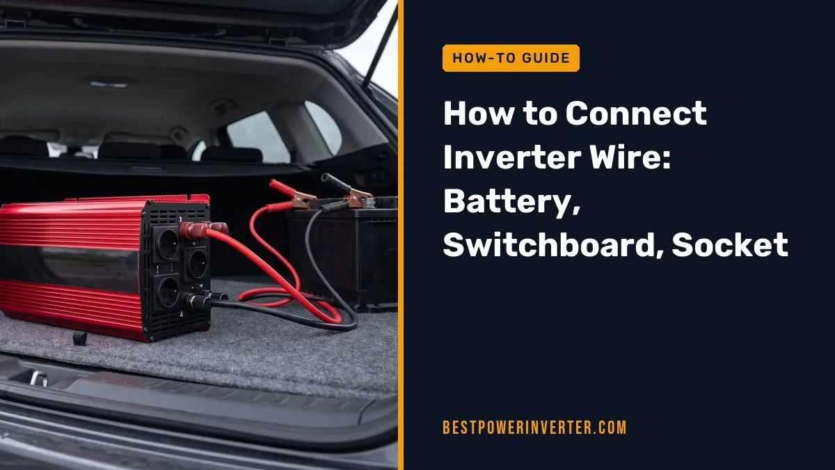
Inverter connection wire must match what your inverter and battery manuals specify for maximum current, cable length, and allowable voltage drop. The battery side needs thick cable, correct polarity, tight terminals, and a fuse close to the battery. The AC side, meaning a switchboard or socket, needs dedicated, protected wiring installed by a qualified electrician.
Quick answer
Read the manuals first. Size the DC cable for the inverter’s maximum current, keep it short, and fit a correctly rated fuse near the battery positive terminal. Never feed an inverter into a normal wall outlet.
- Best for one appliance: plug it into the inverter’s own outlet
- Best for whole-home backup: fixed wiring by a licensed electrician
- An inverter draws far more current on the DC side than its AC watts suggest. A 12 V, 1,200 W unit pulls about 100 A before losses.
- Cable size depends on current, length, battery voltage, and voltage drop. Charts are a starting point, not the final answer.
- Fit the fuse or breaker within about 46 cm (18 in) of the battery positive terminal, as one Magnum manual advises.
- Portable use and fixed household wiring are two different jobs with different rules.
- Backfeeding through a wall socket can injure or kill people. Use a proper changeover switch or a dedicated circuit.
- What Inverter Connection Wire Do You Need?
- What Size Cable Do I Need Between the Inverter and Battery?
- How Does Cable Length Affect Wire Size and Voltage Drop?
- Where Should the Battery Fuse or Circuit Breaker Be Installed?
- How Do I Connect Inverter Wire to a Battery?
- How Do I Connect Inverter Wire in a Switchboard?
- How Do I Connect an Inverter Wire to a Socket?
- Which Spec Decides What?
- How Do I Wire an Inverter Safely?
- When Do You Need a Licensed Electrician?
- Frequently Asked Questions
What Inverter Connection Wire Do You Need?
Most inverter installs use four kinds of wire: DC battery cables, AC output cables, a grounding conductor, and sometimes communication wires. Each one has a different job and different sizing rules.
- DC battery cables: Heavy, flexible copper cables that carry high current at low voltage. These are the thickest wires in the system.
- AC output cables: Standard building wire from the inverter to a switchboard, changeover switch, or socket. Size depends on the circuit breaker and local code.
- Grounding (earth) conductor: Bonds the inverter chassis to earth. Follow the manual and local code for size and bonding.
- Communication wires: Thin signal cables for battery management, parallel units, or monitoring. They carry data, not power, and should be kept away from power cables where the manual says so.
One rule from a grid-connection guideline is worth remembering: do not place DC wiring inside AC switchboards. Keep the two systems physically separate.
What Size Cable Do I Need Between the Inverter and Battery?
Use the cable size printed in your inverter manual, then check it against the battery maker’s limits. SMA states that DC cables must be sized for the maximum battery voltage and maximum battery current, using the battery manufacturer’s documentation.
Here are real examples from one manufacturer manual, the Voltronic Power InfiniSolar VII user manual:
| Inverter size | Battery current | Recommended cable |
|---|---|---|
| 2 kW | 55 A | 6 AWG, about 14 mm² |
| 3 kW | 82 A | 4 AWG, about 22 mm² |
| 5 kW | 137 A | 2 AWG, about 38 mm² |
These numbers belong to that product line and its battery voltage. Another model can need something very different. A Voltronic 3 kVA, 24 V manual lists about 22 mm² (4 AWG) for a 100 A model and about 60 mm² (1/0 AWG) for a 200 A 5 kVA model. Same brand, different answer.
Worked example: why DC current surprises people
Take a 12 V inverter rated at 1,200 W. Divide watts by volts: 1,200 ÷ 12 = 100 A. That is before losses. Inverters are not perfectly efficient. At an assumed 85% efficiency, the battery supplies about 1,200 ÷ (12 × 0.85), or roughly 118 A.
So the cable and fuse must suit well over 100 A, even though the AC side is only about 5 A at 230 V. Higher battery voltage cuts the current. The same 1,200 W at 24 V is about 50 A before losses, and at 48 V about 25 A.

How Does Inverter Cable Length Affect Wire Size and Voltage Drop?
Longer cable means more resistance, and more resistance means more voltage lost along the way. At 12 V, even a small loss is a big share of the total. That is why battery cables should be as short as possible.
You can estimate the drop with a simple formula for copper: resistance = 0.0172 × round-trip length (m) ÷ cable area (mm²). Then multiply resistance by current.
Using the 12 V, 118 A example with the inverter 2 m from the battery (4 m round trip):
| Cable | Resistance | Voltage drop | Share of 12 V |
|---|---|---|---|
| 16 mm² | about 0.0043 ohm | about 0.51 V | about 4.2% |
| 25 mm² | about 0.0028 ohm | about 0.33 V | about 2.7% |
A common design aim is to keep the drop to roughly 2 to 3 percent. The 16 mm² cable misses that. The inverter may also shut down on low-voltage alarms at heavy load, because the voltage at its terminals sags below the battery voltage.
Heat is the other risk. Undersized cable gets warm under load, and loose or poor crimps make it worse. If your run is longer than the manual’s maximum, go up a size or move the battery or inverter closer together.
Where Should the Battery Fuse or Circuit Breaker Be Installed?
Install it on the positive cable, as close to the battery as practical. The Sensata/Magnum N-Series inverter manual warns that a fuse must sit between the battery and inverter to protect against shorted cables. It recommends placing the fuse within 18 inches (about 46 cm) of the battery positive terminal.
Why so close? A battery can deliver huge current into a short circuit. The fuse only protects the cable between itself and the inverter. Any cable between the battery and the fuse is unprotected, so that section should be tiny.
The same Magnum guide gives short-run examples:
- 4 AWG cable with a 150 A fuse for an 80 A, 12 V inverter
- 4 AWG cable with a 200 A fuse for a 120 A model
Notice the fuse is larger than the running current. It must carry normal load and surges without blowing, but still protect the cable. Use the fuse or breaker rating in your manual, and make sure it is rated for DC at your battery voltage. An AC breaker is not a substitute.
A DC isolator or disconnect switch is also smart. It lets you cut power safely before maintenance.
How Do I Connect Inverter Wire to a Battery?
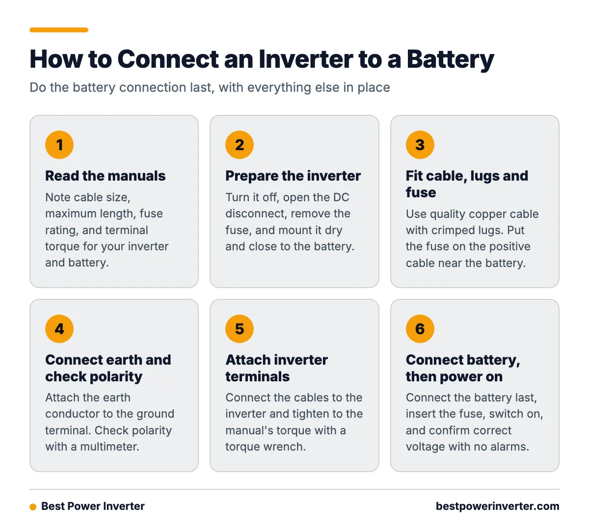
Connect it with the inverter switched off, the DC disconnect open or the fuse removed, and positive and negative checked twice. Positive goes to positive. Negative goes to negative. Do this last, after everything else is in place.
What is the correct positive and negative inverter wire connection?
Red (or marked +) cable runs from the battery positive terminal, through the fuse and isolator, to the inverter’s positive terminal. Black (or marked −) cable runs from the battery negative to the inverter negative. Reversing them can destroy the inverter instantly, and many units have no protection against it.
Battery connection checklist
- Read the inverter and battery manuals. Note cable size, maximum length, fuse rating, and terminal torque.
- Turn the inverter off. Open the DC disconnect and remove the fuse.
- Mount the inverter in a dry, ventilated spot, as close to the battery as the manual allows.
- Use quality copper cable with properly crimped lugs. Do not use pliers or hammer crimps.
- Fit the fuse holder on the positive cable near the battery, within the distance the manual states.
- Connect the earth conductor to the inverter’s ground terminal.
- Check polarity with a multimeter before you connect.
- Attach the cables to the inverter terminals. Tighten to the torque in the manual, using a torque wrench.
- Connect to the battery terminals last. Insert the fuse or close the disconnect only after a final check.
- Switch the inverter on and confirm it reads the correct battery voltage with no alarms.
A small spark when you make the final connection is common. Inverters have input capacitors that charge quickly. Follow the manual for any pre-charge step it requires.

How Do I Connect Inverter Wire in a Switchboard?
The inverter’s AC output goes to the switchboard through its own protected circuit, wired by a qualified electrician. Do not tap into an existing circuit or push power backward into the house wiring without the right equipment.
The reason is safety. If the inverter feeds the house wiring while the grid is also connected, or while the grid is down, power can flow where it should not. Line workers repairing a dead grid line could be shocked by your inverter. This is called backfeeding.
A preview of AS/NZS 4777.1:2024 shows that the standard requires inverter energy systems to connect to a dedicated switchboard circuit. It also addresses overcurrent and RCD protection for associated socket outlets. Other countries have their own rules, but the idea is the same.
Fixed switchboard connection checklist
- Check local rules. Many places require a permit and inspection.
- Choose the design: a changeover (transfer) switch for backup, or a grid-connected setup approved by your utility.
- Install a dedicated circuit breaker or isolator rated for the inverter’s AC output.
- Run AC cable sized for that breaker and the cable length, per local code.
- Connect line, neutral, and earth correctly. Neutral and earth bonding rules vary by system, so follow the inverter manual and code.
- Add RCD or GFCI protection where code requires it.
- Keep DC wiring out of the AC switchboard.
- Test the changeover so the grid and inverter can never be connected at once.
- Label the switchboard and the isolators clearly.
- Powering only a few chosen loads? Wire a separate backup sub-board through a changeover switch.
- Powering the whole house? Have an electrician design the system and check the inverter can handle the total load.
- Feeding power to the grid? Use only a grid-approved inverter and installer.
How Do I Connect an Inverter Wire to a Socket?
There are two cases. For portable use, you plug an appliance into the inverter’s own socket. For fixed use, an electrician wires the inverter to socket circuits through a protected supply. These are not the same job.
Can I connect an inverter directly to household wiring or a wall socket?
No. Never plug an inverter into a wall socket, and never use a cable with a plug on both ends to power your home. Current can flow backward into the grid and energize wires that look dead. It can start fires, damage the inverter, and kill someone.
Portable plug-in checklist
- Check the appliance wattage, including start-up surge, against the inverter’s rating.
- Connect the DC side first, following the battery checklist above.
- Switch the inverter on with nothing plugged in.
- Plug the appliance directly into the inverter outlet, or use a short, rated extension cord.
- Do not daisy-chain power strips or overload the outlet.
- Switch off the appliance before unplugging it.
For fixed socket outlets on an inverter circuit, use dedicated wiring from the switchboard with the right breaker and RCD protection, installed by an electrician.
Which Spec Decides What?
Many people mix up cable size, fuse size, and current rating. This table separates them.
| Item | What decides it | Where to find it |
|---|---|---|
| Manufacturer-specified cable size | Inverter model and battery voltage | Inverter manual |
| Current capacity | Maximum DC input current and cable rating | Inverter and battery manuals |
| Cable length | Layout, plus the manual’s maximum run | Manual and your site measurements |
| Voltage-drop target | Length, current, and cable area | Your calculation; roughly 2-3% is a common aim |
| Fuse rating | Cable size and inverter current | Inverter manual |
| Terminal torque | Terminal type and manufacturer | Inverter and battery manuals |
If the manual and a general chart disagree, follow the manual. Torque values in particular vary by product, so do not guess them.
How Do I Wire an Inverter Safely?
Wire it with the right cable, a DC fuse near the battery, correct polarity, tight terminals, proper earthing, and no backfeed path. Then check every step before you power up.
Common wiring mistakes
- Using a chart instead of the manual. Charts ignore your model’s real current and length limits.
- Skipping the fuse or placing it far from the battery.
- Long, thin cables that cause voltage drop and low-voltage shutdowns.
- Loose terminals. They heat up under heavy current and can melt insulation.
- Reversed polarity. One slip can ruin the unit.
- Using an AC breaker on the DC side. It is not built to break DC current safely.
- Backfeeding through a wall socket. Dangerous and often illegal.
- Mixing DC and AC wiring in one switchboard.
Final pre-power checklist
- Cable size and length match the manual.
- Fuse or breaker is DC-rated and close to the battery positive terminal.
- Polarity is verified with a meter.
- Terminals are torqued to spec.
- Earth is connected.
- AC side has its own protected circuit and, where needed, RCD or GFCI.
- No path exists for the inverter to feed the grid.
When Do You Need a Licensed Electrician?
Call one for anything that touches the house’s fixed wiring or switchboard. That includes adding a changeover switch, a dedicated inverter circuit, or any grid-connected system. Many regions require licensed work and an inspection by law, and insurers may refuse claims after unlicensed work.
DIY is realistic for the DC side of a small portable setup, if you follow the manual. If you are unsure about neutral and earth bonding, breaker ratings, or local code, stop and ask a professional. The cost of an inspection is small next to a fire.
Frequently Asked Questions
How to connect inverter wire in switch board?
Have a qualified electrician wire the inverter to a dedicated, protected circuit through a changeover switch or approved isolator. Add the right breaker and RCD or GFCI protection, and keep DC wiring out of the AC switchboard. Never connect the inverter to a live circuit without isolating the grid.
How to connect inverter wire to battery?
Switch the inverter off and remove the fuse. Run the positive cable from the battery through a fuse and isolator to the inverter positive terminal. Run the negative cable to the inverter negative. Tighten to the manual’s torque, connect to the battery last, and verify polarity first.
How to connect inverter wire to socket?
For portable use, plug the appliance into the inverter’s outlet. Do not plug the inverter into a wall socket. For fixed sockets, an electrician must wire a dedicated protected circuit, usually with a changeover switch.
How to wire inverter?
Start with the manual. Connect the DC cables with the correct size, a fuse near the battery, and correct polarity. Connect earth. Then connect the AC side, either to the inverter’s outlets or to a dedicated circuit installed by a licensed electrician.
What does inverter wire connection involve?
An inverter wire connection has two sides. The DC side links the battery and inverter with thick cable and protection. The AC side links the inverter to appliances or a switchboard. Each side has its own cable, protection, and safety rules.
What is an inverter connection wire?
It is the cable that links an inverter to the battery, the earth, and the AC loads. The DC battery cable is the heaviest, since low-voltage systems carry high current. Size it using the inverter manual, cable length, and voltage drop.
Sources